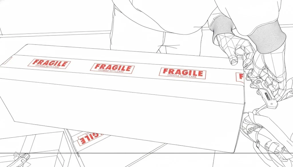
Check all parts are accounted for, and there is no physical or structural damage. If there is, please reach out to with your order details and the part that needs inspection and solution will be provided or a replacement part will be sent.
Set aside any tools that are needed (allen key and socket wrench).
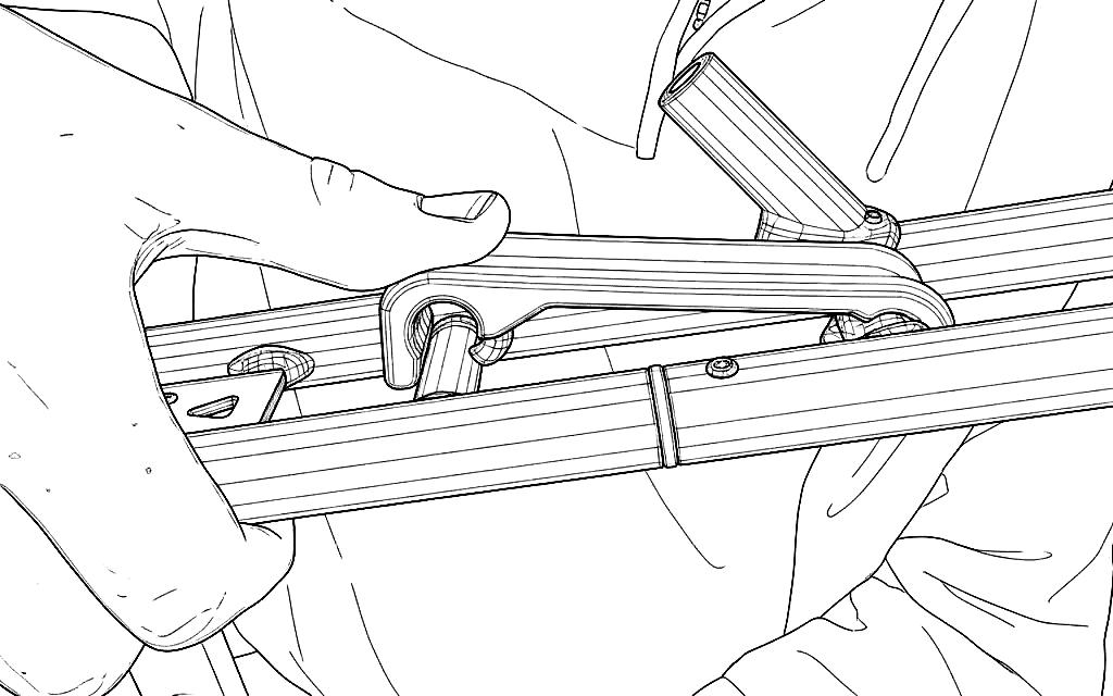
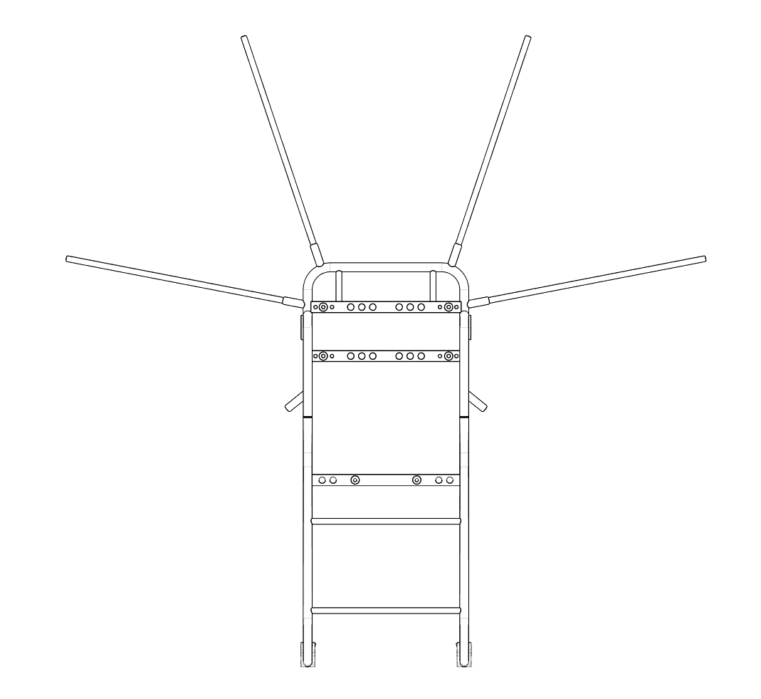
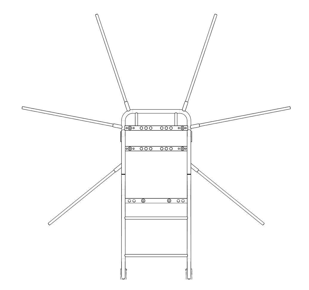
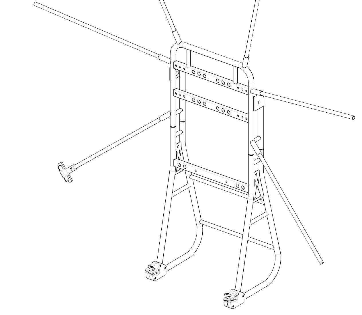
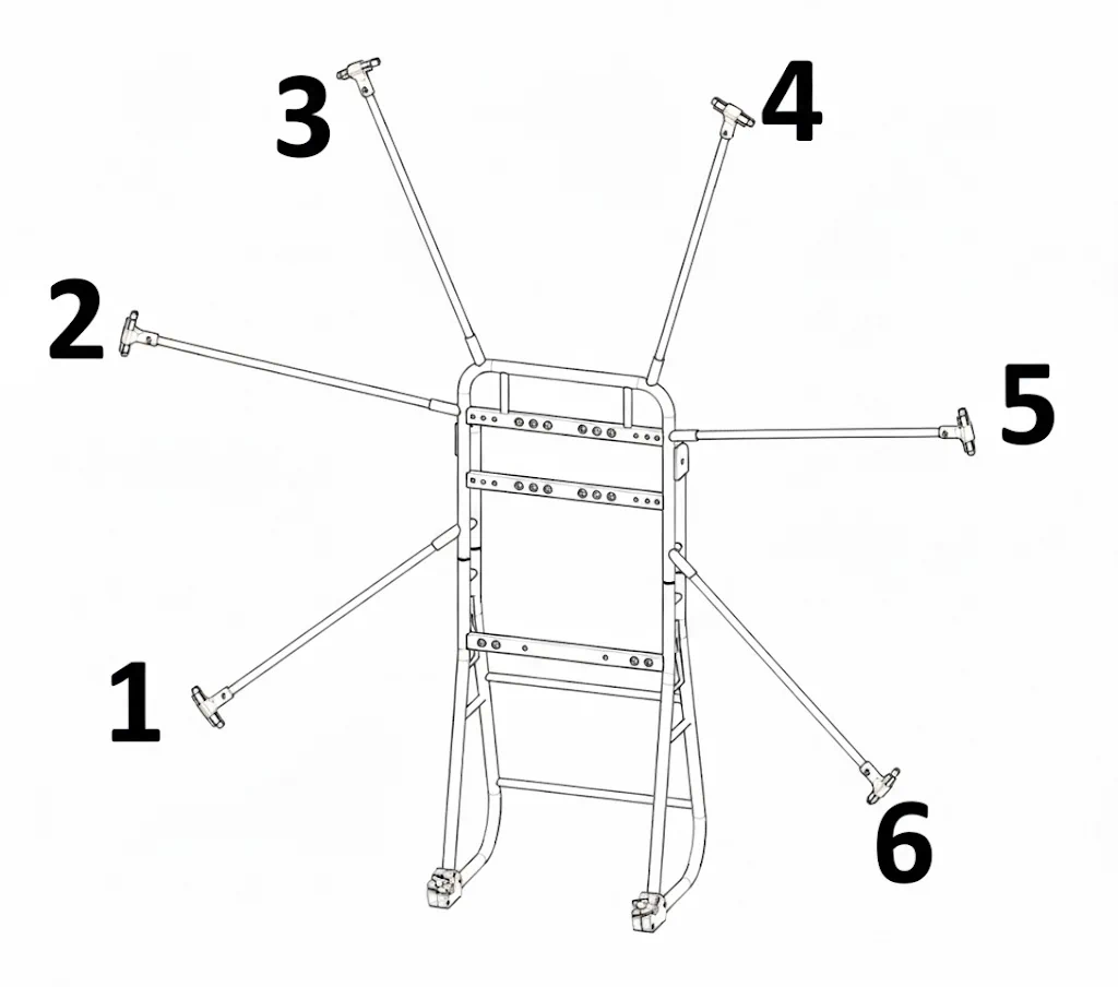
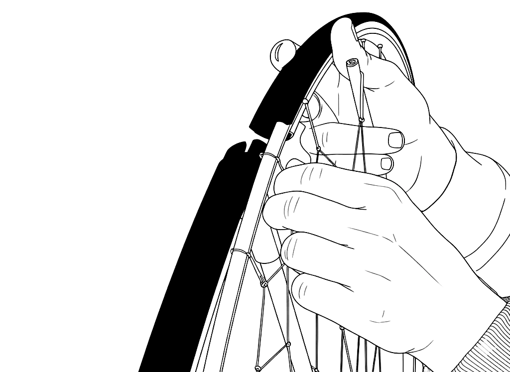
There are 7 total hoop connectors 0-6. Start by looking at the motor side of the frame (backside) starting from the bottom left CF spar with the number 1 labeled connector.
Slide firmly over the CF spar where you should feel it bottom out and not be able to slide on further. You can confirm this with a light tap of a rubber hammer, but please be careful not to hit the edges of the connector as they are more fragile.
Once the number one connector is in place you can now take the number 2 and work your way clockwise around the frame, placing a connector with the corresponding number on each spar.
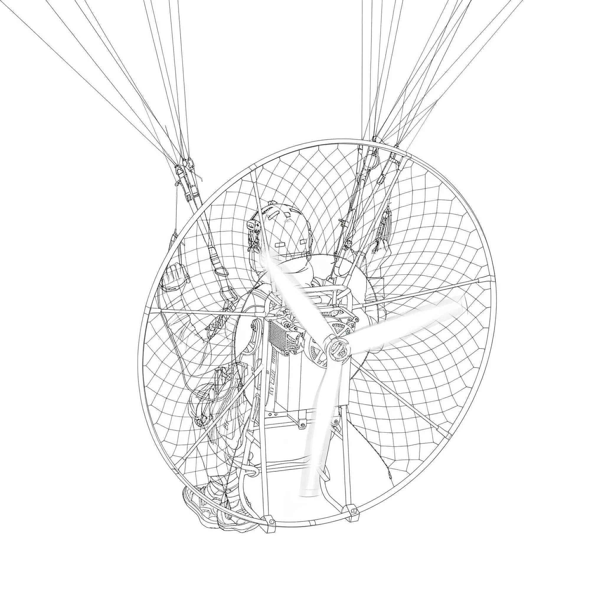
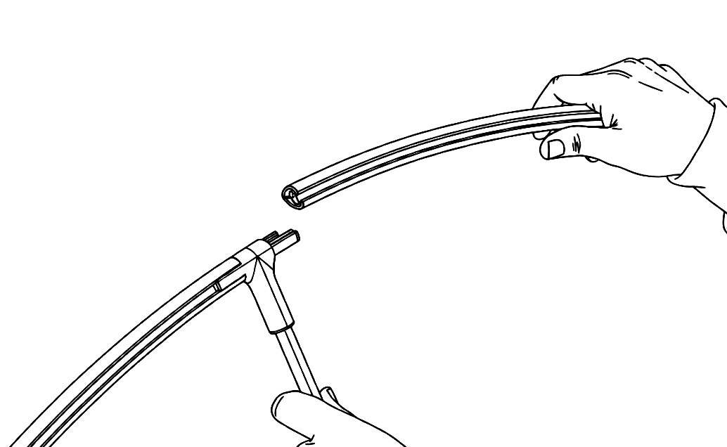
Start by taking the 7 hoop profiles out and sliding onto one section of the connectors, this will allow a simple structure for the netting to slide into place.
Now take the netting out of the bag and count over 6 sections of the netting rod from an end point that will be the middle point to start from. There are 12 total netting rods.
Slide the netting rods into the tubing and work your way down each size symmetrically. It can be done many ways but this is found to be the simplest.
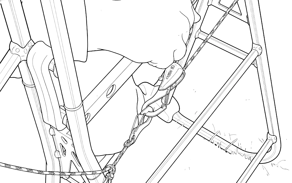
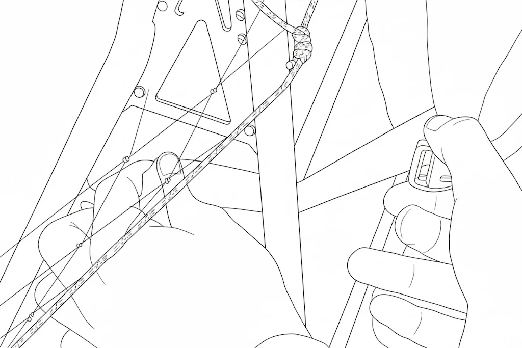
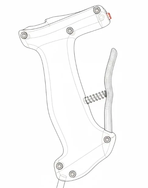
Finally connect the net tensioner and tighten the netting up as desired.
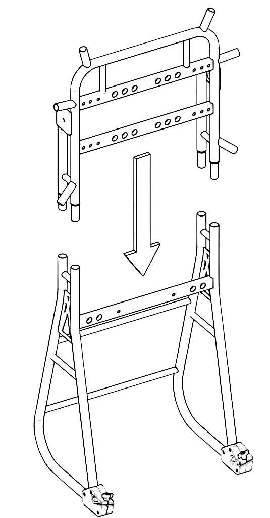
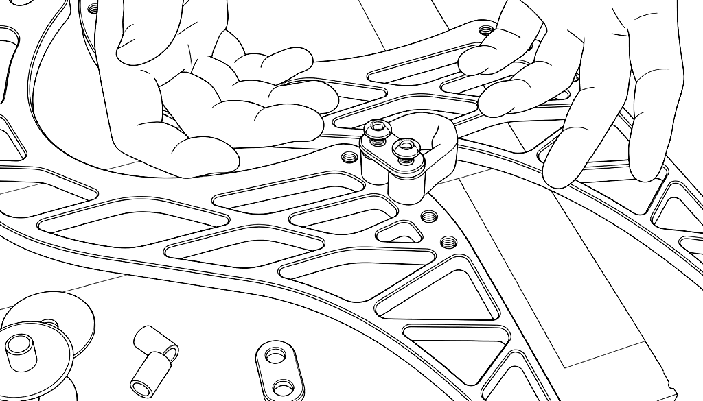
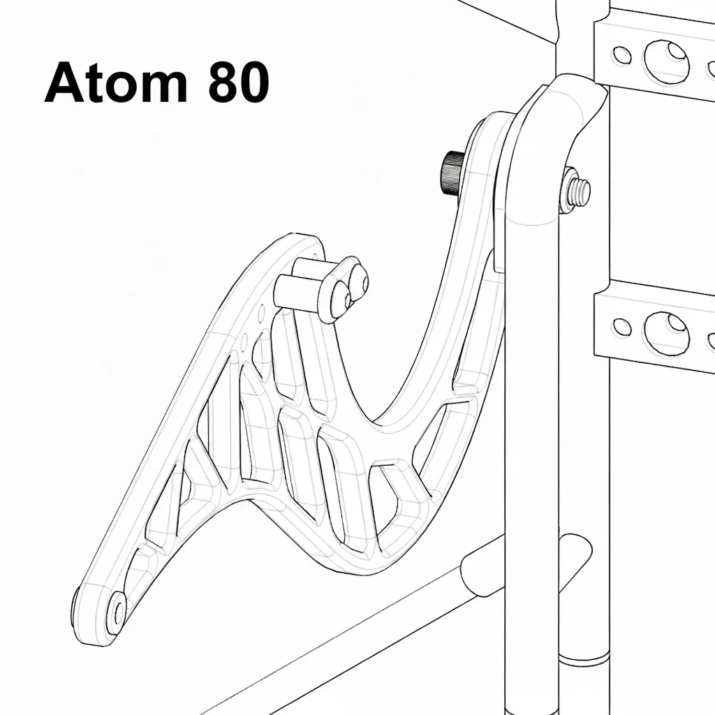
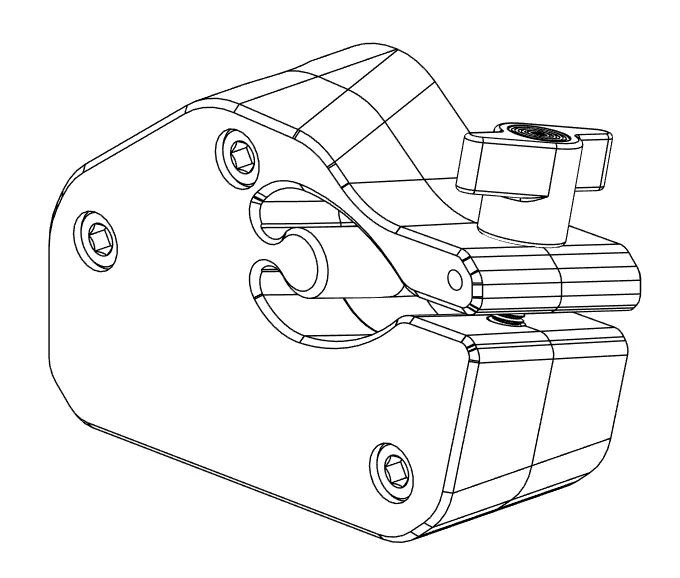
Take your goose neck bars out of protective packaging and then decide which direction you want the torque compensation to be on. For the standard SP140 electric motor direction, it will be on the right side of the goose neck bars when in the flying position. *For the ICE Atom 80, it should be placed on the left side.
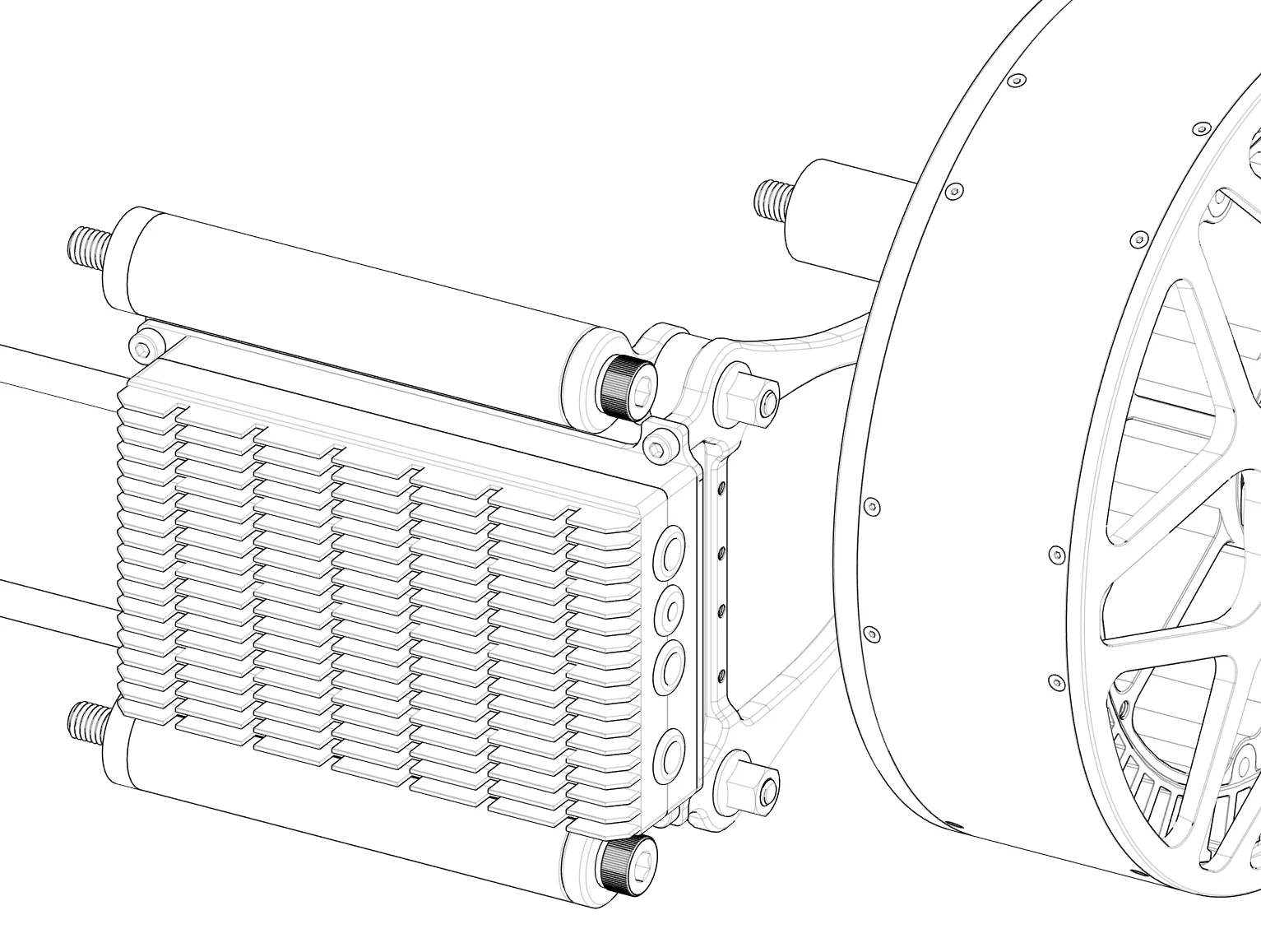
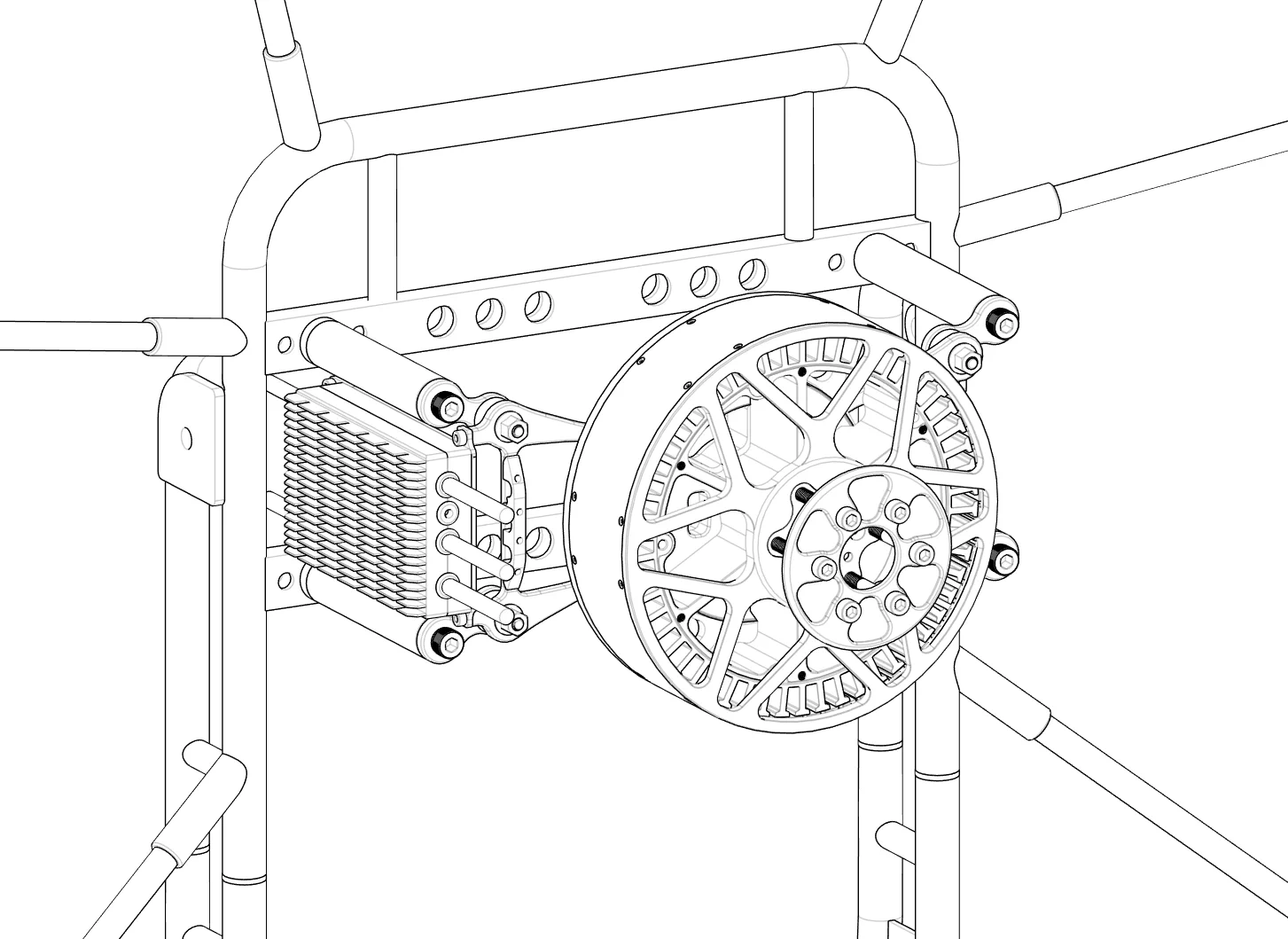
Place the soft links in place using the 2 aluminum standoffs.
Tighten up the bolts holding the soft links (LockTight can be applied). Tighten to 10nm.
Using the plastic washers and 10mm bolt tighten up the goose neck bars to the frame leaving just enough play to move vertically with no wiggle.
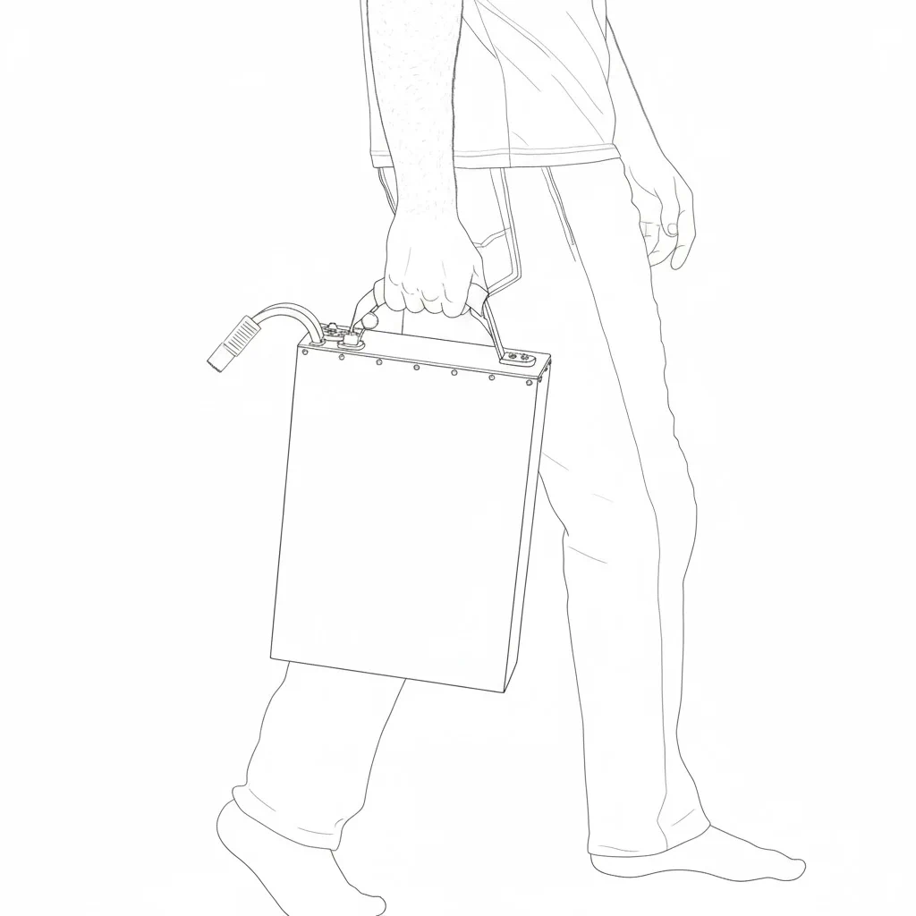
Take the battery pack out of its protective foam case.
Line up the battery pack with the slot and slide down into place.
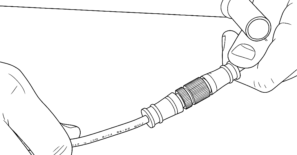
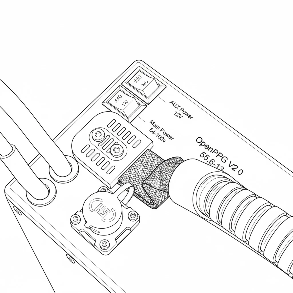
With both switches off, connect the main power connector.
Then connect the BMS data plug to the top of the battery.
You can now turn on the main power switch. This will boot up the system and you will hear some beeps. The screen on the hand controller will show startup info and telemetry data.