Title here
Summary here
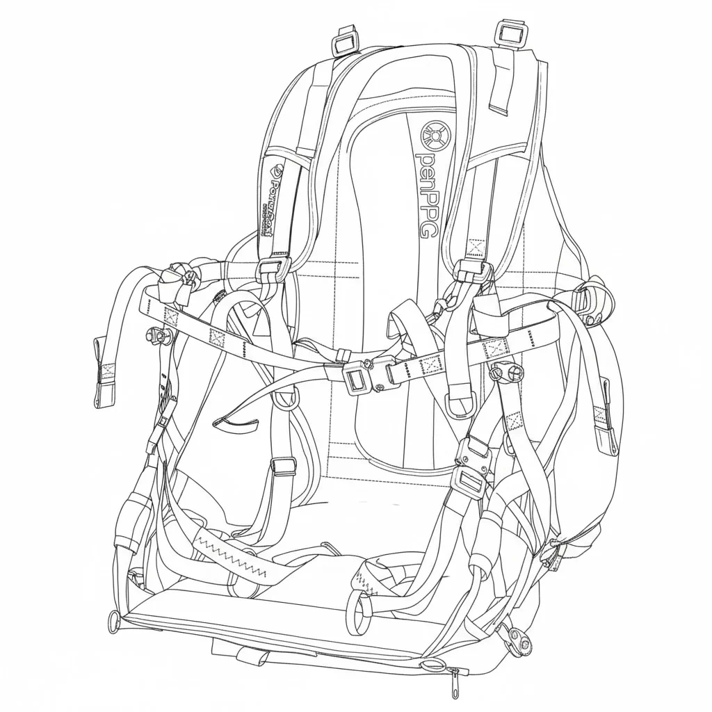
This section helps you identify all the components of your SP140 v2.5 system.
| Component | Description |
|---|---|
| Center Frame | Main structural hub |
| Center Frame Legs | Lower support structure |
| Frame Hoop Section | Protective cage segments |
| Hoop Connector | Numbered connectors (0-6) |
| Center Frame Clamp | Secures frame assembly |
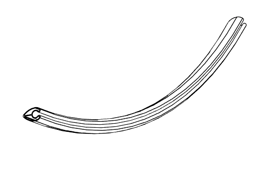
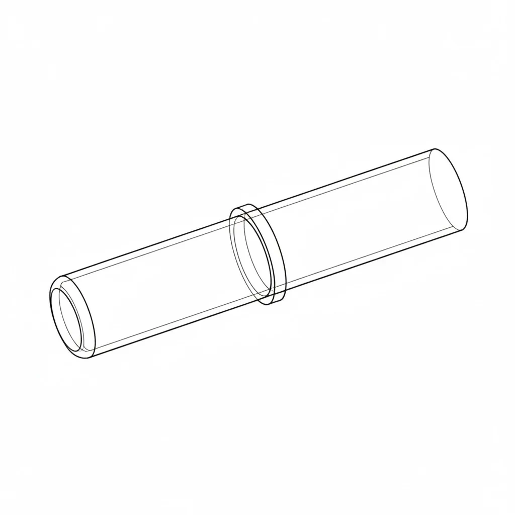
| Carbon Fiber Spar | Lightweight structural rods |
| Leg Clamp | Secures legs to frame |
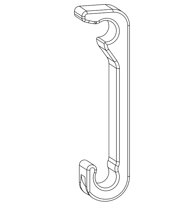
| Goose Neck Bar | Torque compensation bars |
| Netting Rod | Supports protective netting |
| Netting | Dyneema safety netting |
| Center Frame Connector | ABS connection pieces |
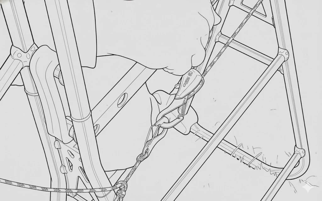
| Harness | Pilot support system |
| Component | Description |
|---|---|
| Motor | OpenPPG v2.5 25kW brushless motor |
| Motor Mount Plate | Secures motor to frame |
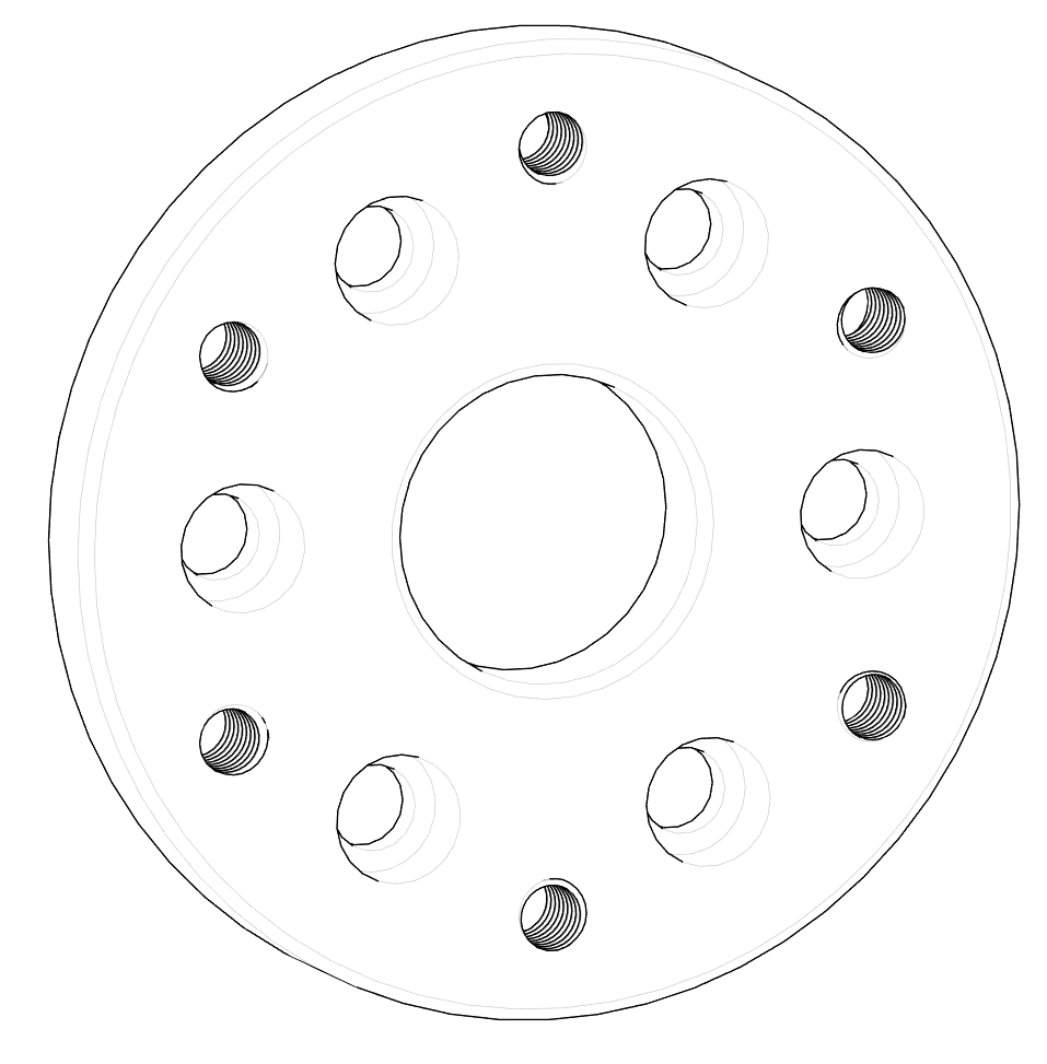
| Prop Plate | Propeller mounting interface |
| Prop Adapter | Connects prop to motor shaft |
| Component | Description |
|---|---|
| Motor Controller | ESC (Electronic Speed Controller) |
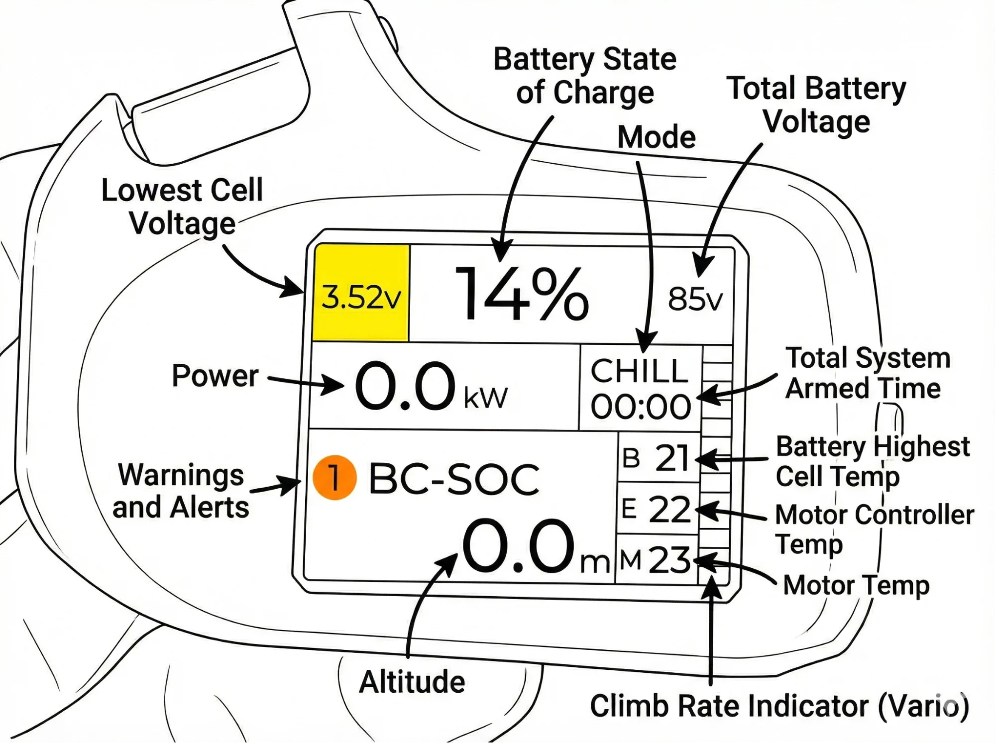
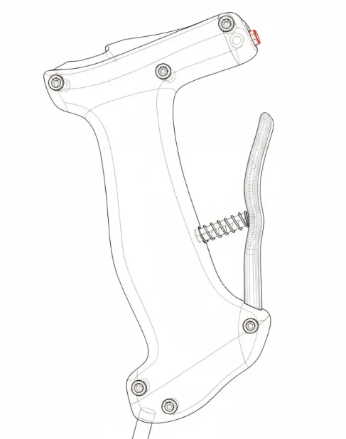
| Hand Controller | Throttle and display unit |
| BMS Data Plug | Battery management system connection |
| Main Power Connector | High-current battery connection |
| Component | Description |
|---|---|
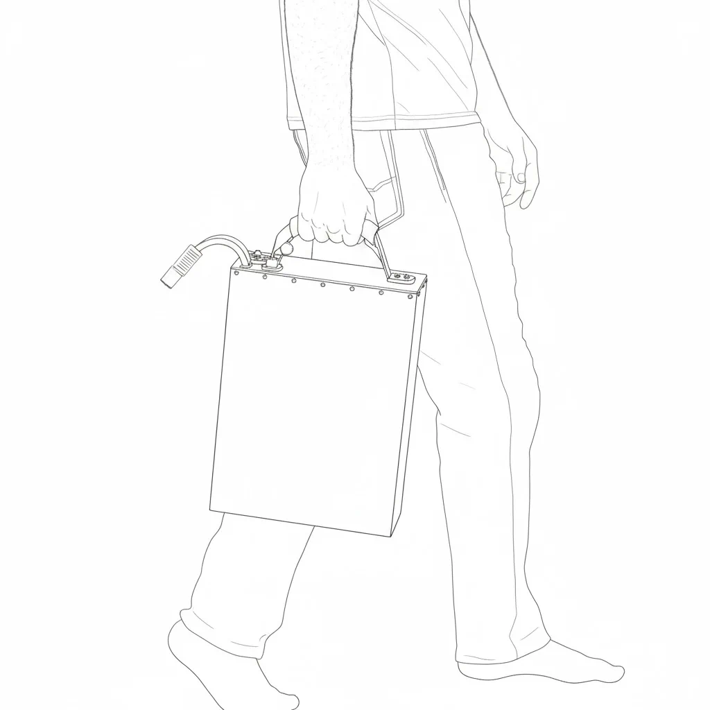
| Battery Pack | 2.6 kWh or 4.8 kWh options |
| Battery Standoffs | Mounting hardware |
| Main Power Switch | On/off control |
| BMS Port | Battery management interface |
| Component | Description |
|---|---|
| Quick Release Prop Hub | Tool-free removal system |
| Propeller | 140cm carbon fiber (bi-blade or tri-blade) |
| Prop Bolts | Secure prop to hub |
| Component | Description |
|---|---|
| Charger | AC to DC battery charger |
| Charge Port | Battery charging connection |
| Status Indicators | LED charging status display |
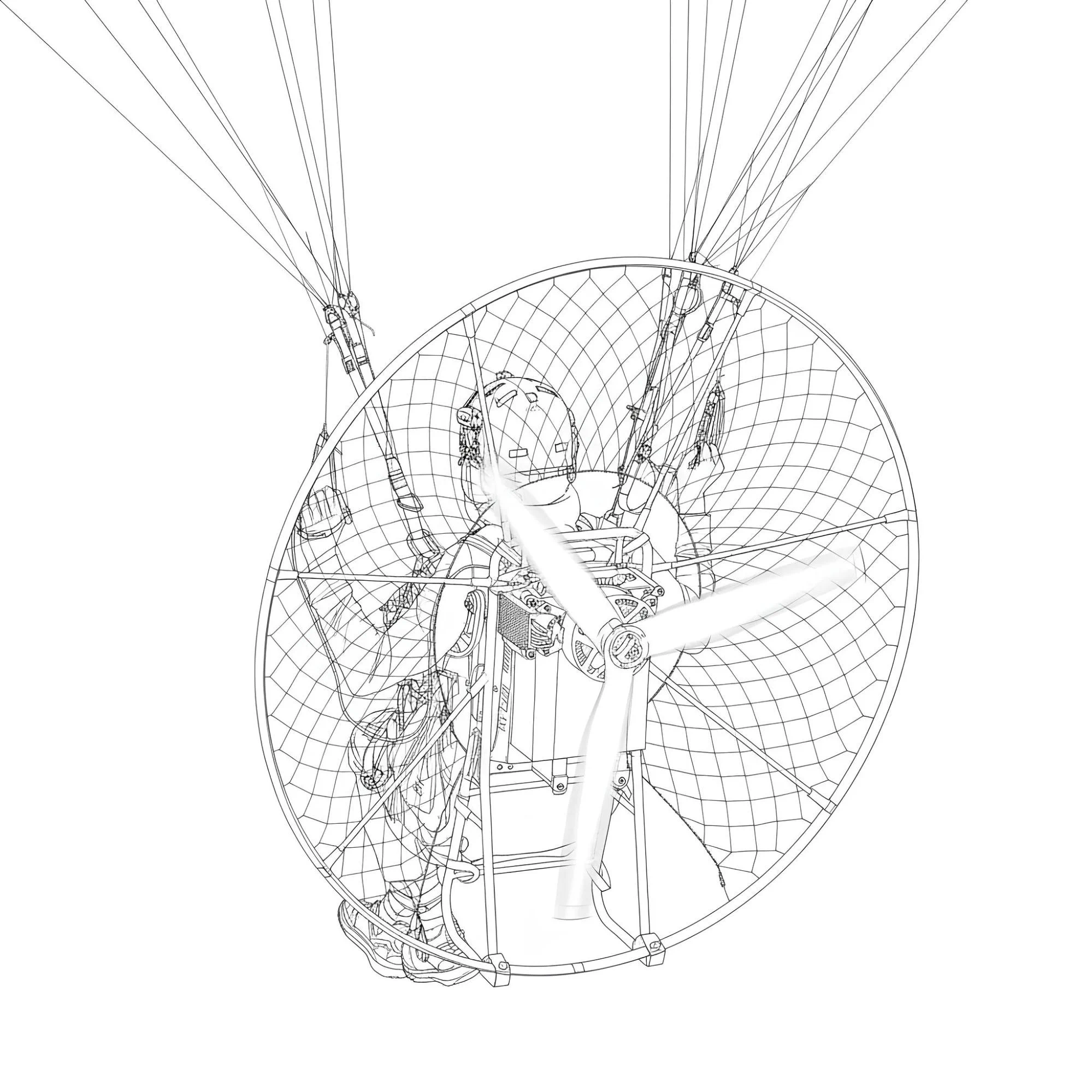
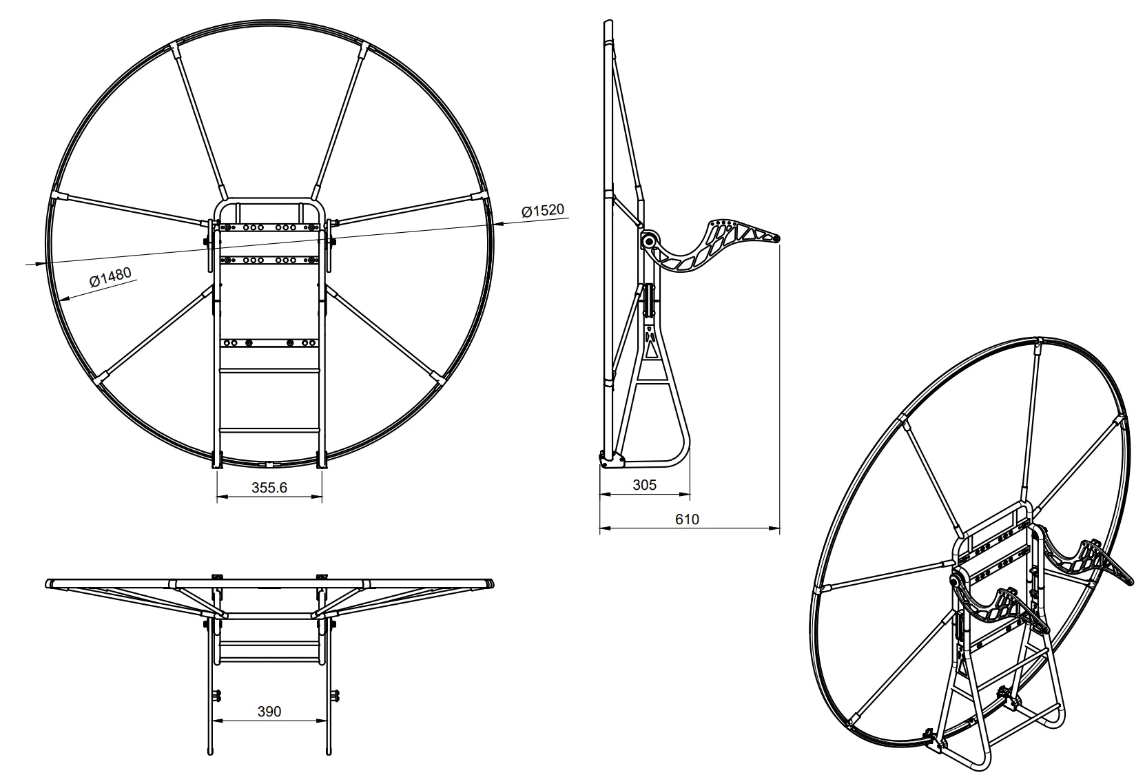
From the front (prop side), you can identify:
From the side, you can see:
From the back (pilot view), you can identify:
The power system consists of:
When unboxing, verify you have received:
Frame Components:
Power System:
Hardware & Tools:
If any parts are missing or damaged, contact with your order details.